
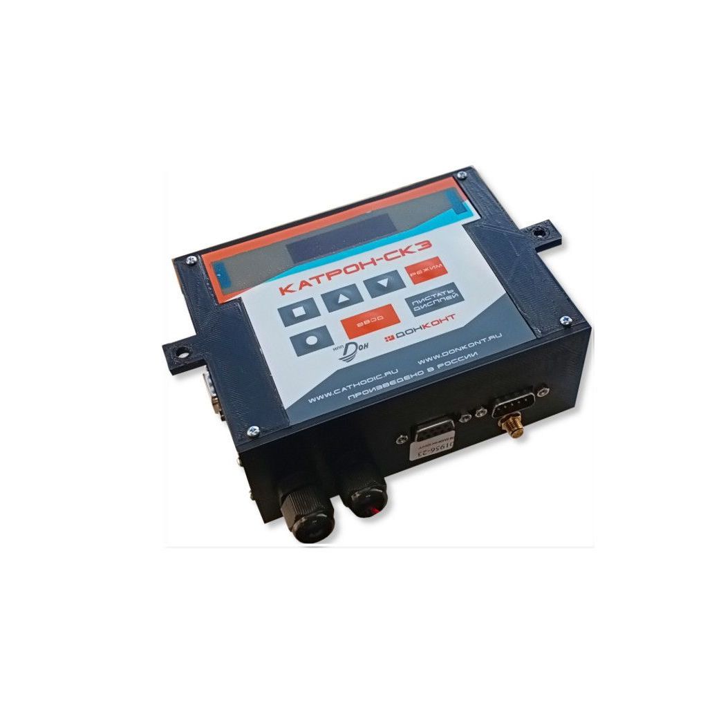
KATRON-SKZ controller
The KATRON-SKZ controller for remote monitoring and work control of a single phase CP rectifiers
from 42 352 RUR
Characteristics
Controller
Number of analog inputs
3
Supply voltage, V AC
from 8 till 12
Number of discrete (relay) inputs
8
Current consumption in the main mode, no more than, mA
100
Number of temperature sensors (integrated into the microcontroller)
1
Current consumption in power saving mode, no more than, mA
30
Number of phone numbers may be recorded in the controller
4
Current consumption in communication session mode, no more than, mA
400
GSM/GPRS cellular module or RS-485/RS-422/CAN serial port interface (removable, interchangeable modules)
1
Operating temperature range, deg. C
from minus 40 to plus 50
Overall dimensions without protruding elements (LxWxH), no more than, mm
135х120х60
GSM/GPRS module
GSM standard
EGSM(900)/GSM1800
Maximum radiated power (EGSM)
33 dBm ± 2 dB
Minimum radiated power (EGSM)
5 dBm ± 5 dB
Maximum radiated power (GSM1800)
30 dBm ± 2 dB
Minimum radiated power (GSM1800)
0 dBm + 5 dB
Analog-to-digital converter (ADC)
ADC resolution
up to 17 bits
Sampling frequency
up to 10 per sec.
ADC input signal range:
• channel #1 (voltage measurement)
• channel #2 (current measurement)
• channel #3 (potential measurement)
from 0 to 1.55 V
Reference Voltage Instability (Typical Value)
0,0015 %/ºC
ADC nonlinearity (deviation from a straight line drawn through the minimum and maximum values)
from 0,015 to 0,060 %
ADC zero drift
from 1 to 2 mkV/°C
Op-amp zero drift (typical):
• channel #1 (voltage measurement)
• channel #2 (current measurement)
• channel #3 (potential measurement)
1 mkV/°C
Controller input voltage:
• channel #1 (voltage measurement)
• channel #2 (current measurement)
• channel #3 (potential measurement)
from 0 to 75 mV
from 0 to 5 V
Input resistance of the controller:
• channel #1 (voltage measurement)
• channel #2 (current measurement)
• channel #3 (potential measurement)
> 100 kOhm
> 1 kOhm
> 10 МOhm
Input capacity of channels No. 1, 2 and 3 of the controller:
0,1 µF
Built-in temperature sensor
Measured temperature
from minus 40 to plus 99 °C
Resolution
1 °C

SPE Don Ltd. 2008 — 2025 ©
Site is created by support of ESAproject
+7 (863) 248-60-37
info@cathodic.su
info@cathodic.su